
So you have bought a IIc +
The IIc+ was the last Apple II to be released (Unless you count the IIe card for the LC Series Macs) it had a 4MHz Zip Accelerator in it and could be booted up into 1MHz by holding the esc key on boot.
These units have become quite popular with collectors of vintage computers but due to them only being released in North America a 240v version was never produced, this limits their usability in countries on different voltages.
I set out to fix this by replacing the internal power supply with an auto switching 100v - 240v power supply. So lets get to it.
The Specs on the original power supply are +12v@0.9A +5v@1.9A and -12v@0.15A the new one is +12v@2A +5V@6A and -12@0.5A. Not sure what I am going to do with all that extra power... RGB LED’s anyone...
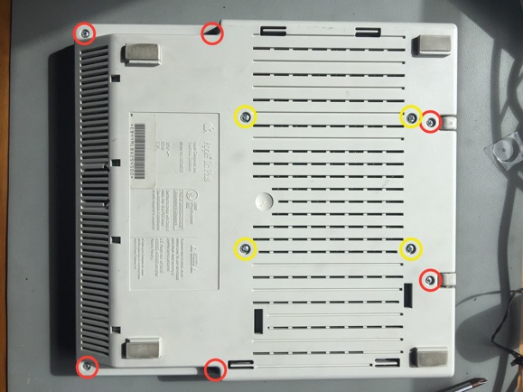
Step 1: Turn it upside down and remove the screws, The 6 red circles hold the top case on and the 4 yellow circles hold the floppy drive in. you don’t need to remove the floppy drive screws at this stage, but i did so I could remove everything and easily work on what I needed to.
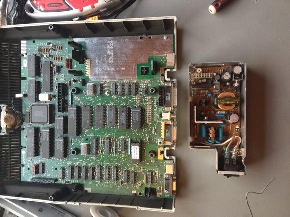
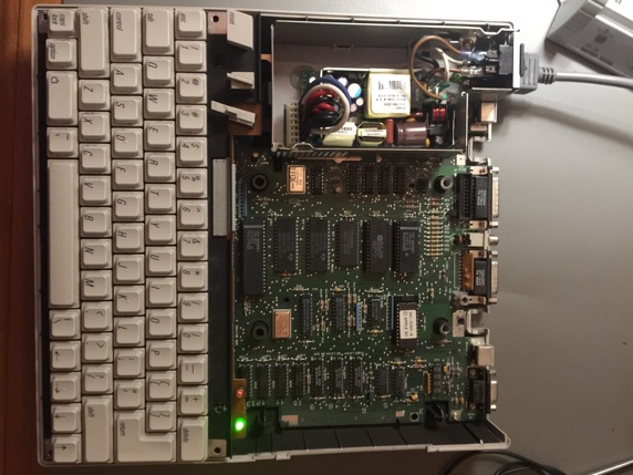
Step 2: The Picture to the right shows the IIc+ fully disassembled, the keyboard just lifts up and unplugs, the floppy drive has 2 connectors one for data and one for the drive activity light. I have also removed the old power supply case, it has a couple of plastic clips holding it in but lifts straight up once you hold them open a little. I have actually taken the lid off the power supply case as well, this is held on with two smaller screws.
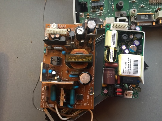
Step 3: WARNING - some Voltages inside the power supply case are HIGH VOLTAGE and I only recommend proceeding if you feel comfortable working with high voltages and understand the risks, NEVER work on the power supply while it is plugged in. Now thats out of the way I have removed the old board and have the old and new side by side. The new board is an EOS VLT40-3200 and can be found for reasonable prices online
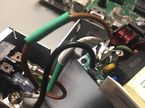
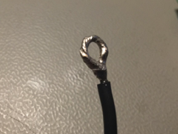
Step 4: I have cut the wires off the old board and taken it out of the case and started to solder and heat shrink the AC side of the new board. For the ground wire I soldered one side and made a loop by tinning the other side (below) to attach the ground to the existing screw point.
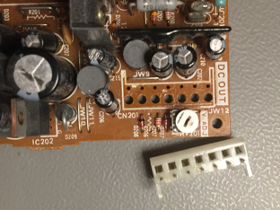
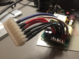
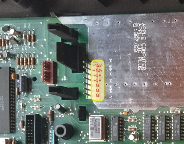
Step 5: I de-soldered the old DC out Connector and rewired it to the new power supply, The pinouts on the IIcPlus go from Pin 1 -12v, +12v, +5v, +5v, G, G, G and the pinouts on the new supply went +5v, +5v, G, G, -12v, +12v. so before plugging into the IIc + I double checked everything with a multimeter.
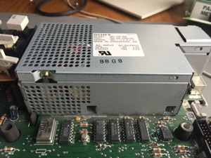
Step 6: I Secured the new board into the case with some double sided tape and hot glue, probably some proper standoffs would have been better but it is what I had on hand and in the end was quite secure. I then plugged it in for a quick power on test (I really should have had the lid back on the power supply case at this stage - BE CAREFUL, there is live 240V on the plug side, even with the switch off.
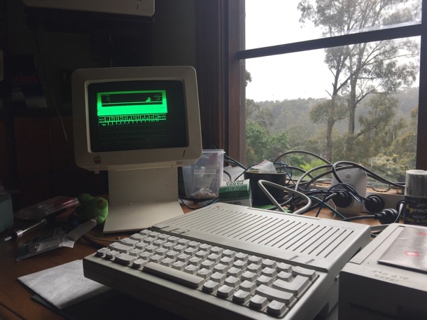
Anyway - it Beeped and I got a green light - Woot, Time to find a monitor.
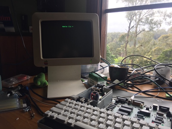
I quickly plugged in a monitor and everything looks good, time to reassemble.
Screwed the top of the power supply case back on, no one will ever know what lies beneath...
All back together, I am very happy with my universal world wide capable IIc+. I do need to call out that Mark Wise had a universal power board created that is basically a drop in replacement for the old board, if I had my time again I would have definitely purchased one of those, it would have saved much of the soldering but at the time I bought mine I didn’t know such a high quality option existed. If you are planning on doing something similar and can’t get hold of one of Mark’s great creations then this isn’t a bad second option.
Ms. PacMan 1MHz
Ms. PacMan 4MHz
Apple II Forever.
