
A tale of repairs on an Applied Engineering Vulcan IIGS Power Supply and a Vulcan //e interface that were brought back from certain death.
*Shariel is the name given to the Vulcan God of Death in Star Trek (TM)
By Mark Cummings
Historical records
It all started back in the year 2000, when I was fortunate enough to grab several bargains at a goodwill store in Townsville. Lots of collectable Apple II series computers and some rare peripherals. One of those was an Apple IIGS which had an Applied Engineering Vulcan IIGS 40MB drive installed which I recognised straight away. I always wanted a hard drive in my Apple //e or Apple IIGS computer back in the day but they were prohibitively expensive so it never happened.
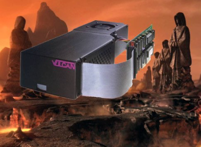
A Vulcan IIGS Hard Drive and interface land on Vulcan on their final journey
Keen to test out my newly acquired gem I connected it all up and turned the power on and the fuse blew immediately. A replacement fuse was installed and that also blew immediately.
A quick look inside revealed nothing obvious so I tested some parts inside with a multimeter and found nothing out of the ordinary. I traced out part of the circuit on paper but realised this was a big task which I was not prepared to do at the time.
Circuit Diagram created with Protel Schematic application

An Olive branch
I was fortunate enough that another Apple II user Craig Bradley kindly offered to loan me his Vulcan drives (yes two of them) for testing, recording and cross checking the circuit diagram, and this would also allow me to compare parts and variants and potentially help find the fault with my own PSU.
I gave both of Craig’s PSUs the once over and found a few minor issues, mostly physical damage caused by someone previously, and because the parts are crammed into the enclosure. I found that one leg of a Y capacitors (C3) had pulled out of one board, and one inductor (L3) had it’s base broken off in another, both likely occurred during reinstallation into the enclosure. All issues were easily repaired except for L3 which now has a lower inductance but seems to work fine.
I wanted to measure the winding resistance on the SMPS transformer before I power it up, so that I could compare results with mine and in case something went bang later. I removed the transformer and found the winding resistance and inductance on Craig’s transformer was identical to mine, leaving me confused about pin 1. Were they both faulty ? Why did it have enamelled copper windings on it that seemed to go nowhere in the transformer ? Even if one of the wires on that pin had broken internally, what about the other wire, surely they weren’t both broken. I mentioned this problem on Apple II IRC one night and one of the other regulars pointed me in the right direction with a few web links, and this revealed my total lack of knowledge on SMPS transformers and their operation.
Apparently it is common to have a winding in the SPMS which is connected to a primary side DC rail, such as the rectified mains DC in this case. The purpose of this is to create an AC ground for any parasitic capacitive currents to reduce electrical noise. I had never heard of this nor run into this on any of the other Apple II SMPSs. Most had a ground wire to chassis earth which I believed was for safety reasons in case of an internal short. So my SMPS transformer may be fine after all.
Confident that it was unlikely that both SMPS transformers were faulty I refitted my transformer onto my PCB. Because I wanted to measure some of the DC voltages for the circuit diagram, I needed to connect multimeter probes onto various parts while switching the PSU on. Unlike the other Apple II PSUs I had done in the past, this was going to be very awkward and potentially dangerous in the Vulcan PSU simply because of how crammed everything is once assembled.
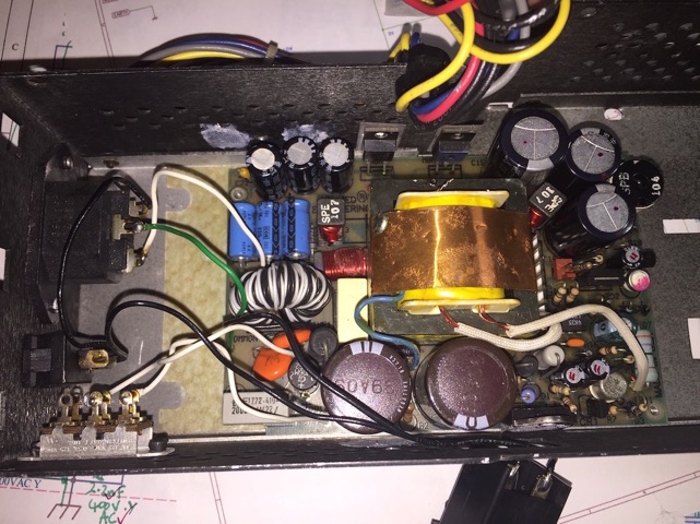
This is how the PSU was before I started round 3 of fault finding. Up to this point I had only replaced a few parts and several fuses. The Fuse holder on the bottom right has to be pulled out in order to slide the PCB out.
After major surgery the SMPS transformer is finally out. I thought this was the fault and that it would be almost impossible to replace or repair.
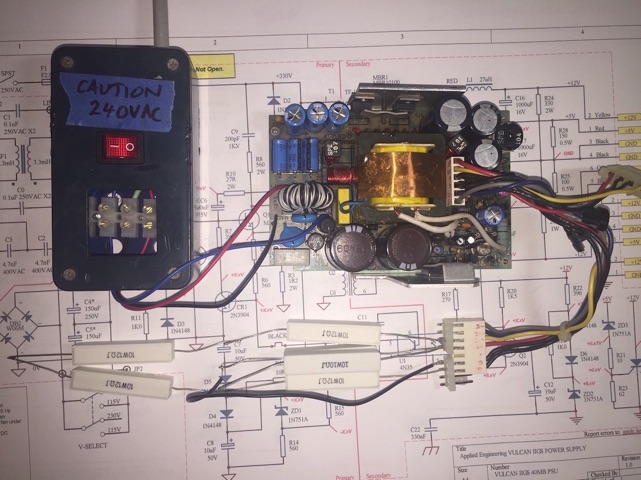
Test jig used to power up and test the PSU board and record voltages. The load bank made from several 10W resistors.
the original filter looking OK from the outside,
but not so good inside
A fibreglass separator is epoxied into place with a small amount of thin set epoxy and left to cure in a plastic tray.
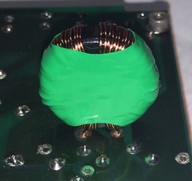
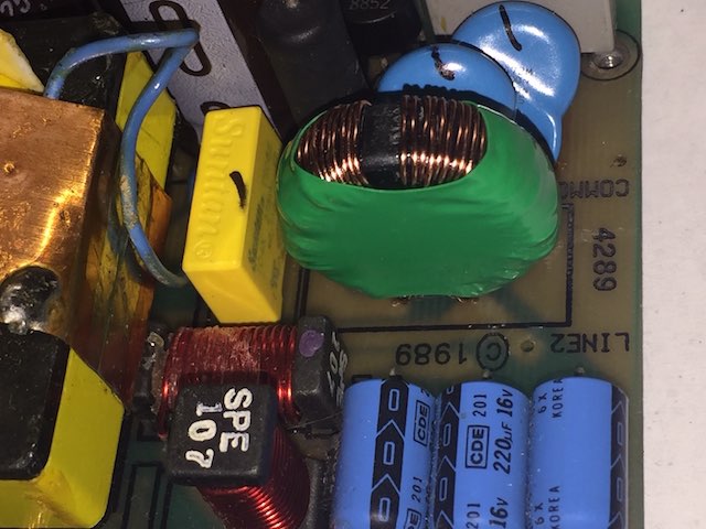
The Common Mode filter on the later model PSU
Try again much later…
Skip forward to 2016 when I had built myself an ESR meter from an Altronics kit and a had little more confidence and experience repairing Switch Mode Power Supplies (SMPS), I thought I’d go over all the electrolytic capacitors which I had successfully done on other Apple II power supplies with relatively good results. Hoping to find the hidden fault in minutes, I only found a couple of capacitors with high-ish ESR but were within tolerance. I also removed several transistors and diodes from the board and they tested out fine. I decided to replace a few selected capacitors anyway and put in a bigger fuse (3 Amp slow blow instead of the original 2 Amp fast blow), and tested the power supply again which immediately vaporised that fuse too. I even vaporised a 10 Amp fuse hoping to prompt the faulty part to reveal itself, but no joy.
2020…
It’s now 2020, I’ve retired, and I’ve been smashing out circuit diagrams for most of the Apple II series PSUs like I was in an arcade playing WhacAMole. It’s time to get this puppy done, even if it means I can’t repair the PSU, at least I will have a decent diagram and so will the rest of the Apple II community.
I created the PCB overlay and circuit diagram in the same way as usual and published them here on the Apple II Oz project pages not long ago.
Since I wasn’t able to keep the power on to check any voltages, I decided to remove all transistors, zener diodes and the SCR and test them separately in a custom circuit in a breadboard circuit to confirm their functionality. This was more of a shotgun approach at finding the fault, but I didn’t see any other way forward. To my dismay not one part tested was faulty.
While I was doing the diagrams I needed to remove several parts including the SMPS transformer so I could get access to parts under the transformer. This is no trivial task as it has 21 connections to the PCB all up, 16 of which are pins bent over and are difficult to remove without causing track damage. Once I had the transformer out of the board I took the opportunity to record the winding resistance and winding inter-connectivity.
There was one outstanding issue I had with the circuit diagram before it was completed, and that was in regard to pin 1 on the SMPS transformer which didn’t seem to connect to any other pin. I thought that may be the fault I was chasing, but what could I do about it other than finding another transformer, and these are custom wound specifically for this Vulcan PSU. If you investigate how to wind your own SMPS transformer like I did, it’s not an easy task. It’s now 31 years since these were made, and Applied Engineering have closed their doors long ago.
To solve that problem I made up a separate fused switch box out of an old ‘jiffy’ box, that I could terminate the Active, Neutral and Ground wires from the PSU PCB into a terminal block, then simply turn a switch on or off easily without risking shorting any parts out and making it safer to measure. I used an illuminated switch on my switch box so I could remind myself that the power was on.
I fitted 4 PCB standoffs to hold the PCB off the bench and made a custom aluminium heat sink with a plastic insulator on the bottom to prevent potential shorts with component legs on the track side. The heat sink was for diodes MBR1, MBR2 and the main switching transistor Q1.
I also made up a load bank using some 10W resistors so I could test the PSUs. This placed about a 1A load on the +5V output and 250mA on the +12V output. There is no need to load the -5v and -12V line as they are barely used in most Apple //s anyway, Apple II Plus excepted.
I reassembled my PSU and connected it up, turned it on and… pffft!, another fuse vaporised and gone to meet its maker.
Another Vulcan soul on the deathbed…
I was aware that some of Craig’s Vulcan PSUs and interface boards hadn’t been tested fully, but I eventually got to test the interfaces, once I had finished all the PSU repairs. My first tests were with the Vulcan IIGS interface with VLGL2.0GS ROM. Using my Apple //e-GS Platinum with DynaComp PSU, I fitted Craig’s Vulcan IIGS controller with an IDE-CF* adapter and +5V power lead. I then inserted a pre-partitioned 512MB CF card that Craig had supplied. I booted the Vulcan IIGS into GS/OS 6.04 and it worked fine, mounting 4 volumes on the desktop.
*More about the IDE-CF interface and partitioning the CF card in a separate article.
A new theory…
Now suspecting that the fuse was blowing on power-up because the crowbar circuit (consisting of SCR, ZD3, R21 and R23) is detecting an over-voltage condition and shorting the +12V rail, and possibly causing the fuse to blow, I disabled the crowbar by removing R21 from the Gate of the SCR. In the Vulcan PSU the +5V rail is adjustable and it looks to me like the voltage could be set too high and cause the crowbar to take effect potentially as low as 5.1 Volts. Confident that this would be the fault this time I tried again.
Installing another 2.5A fast blow fuse, the closest I had in my stock of parts, I turned the power back on and immediately the fuse blew and I saw some sparks in the vicinity of the Common Mode filter FL1 and the SMPS transformer T1. A clue at last. I didn’t want to have to remove the SMPS transformer again, remembering that there is 21 connections on that sucker. Taking an easier route I thought I’d remove the filter instead and use my recently acquired Insulation tester (aka Megger). I tested it out of circuit at 500VAC connected on the Active And Neutral wires and it read 0.2M Ohms (200K Ohms) on the meter. That sounds too low, but I haven’t used this meter before and it’s only a cheap $50 model so maybe I’m getting a false reading or doing something wrong. A good reading would be over 1M Ohm or even over 10M Ohm from more expensive meters I’ve used before.
To be sure, to be sure…
I can’t see anything physical wrong with filter FL1, so I installed it back into the circuit and removed the bridge rectifier DB1 for retesting. This effectively removes all of the circuit past the bridge but I want to see if the fuse blows which will point directly at FL1 being the culprit or not. The only other parts left in circuit are X2 and Y capacitors and they tested OK previously. I had to be careful afterwards because there is no discharge resistor for C0, C1, C2 or C3, a bit of a design oversight by Applied Engineering that I might do something about later. All it needs is a suitable bleed resistor added.
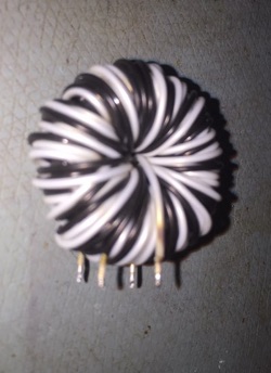
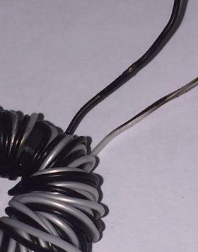
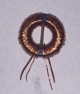
Not being sure what will happen, and just like in the movie Flight of the Phoenix using up all the cartridges, I’m starting to run out of 2.5A fuses by now. I turned the power on and immediately another fuse blew and I got an even larger flash from around filter FL1. Finally I’m getting somewhere. Strange that on the other Vulcan IIGS supply this very same filter is wound completely different, properly wound with Active and Neutral on separate halves of the toroid core using enamelled copper wire instead of the black and white Kynar type wire used in mine. It’s also a different inductance, about 10mH vs 3.3mH on mine. Time to find a replacement or make a new filter from scratch.
On the later model filter I counted 54-1/2 windings of 26 AWG (~0.4mm dia) enamelled copper wire on each half of the toroidal core. I find out later the original filter also has about 53 turns of 0.6mm tinned Kynar type wire.
Are we there yet ?…
To make sure that I have identified the faulty part I installed the good filter FL1 from Craig’s Vulcan PSU and reinstalled bridge rectifier DB1. For now I will leave the crowbar circuit disabled in case the +5V is set incorrectly and trips the SCR. Another fuse goes into the holder and with a 500mA load on the +5V output and 250mA load on the +12V output I’m ready to turn it on, hopefully for the last test.
Power on and… finally… no sparks!, the fan starts up and I have +5.15V on the +5V output and +11.54V on the +12V output. Increasing the load to 1 Amp on the +5V rail and 500mA on the +12V rail only alters the voltages slightly. Now I have a working supply, or at least once I replace the borrowed filter FL1.
Rotten to the core…
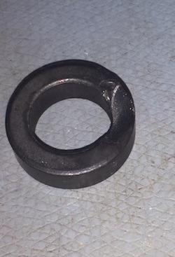
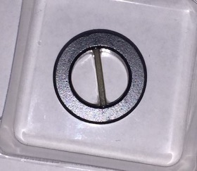
The core with a chip out of it
While I was unwinding the faulty filter FL1 I finally found some scorch marks and some exposed copper where the Active and Neutral wires must have arced. This was only detected with a Megger test earlier and not on my multimeter. When I finally unwound all 53ish turns of Kynar style wire I discovered that the toroidal core had a chip out of it leaving sharp edges. That must have led to the insulation being compromised. This thing was faulty at manufacture, and it was just a matter of time before it cut through and arced out. In later models, they had changed the filter to one with a plastic shell over the toroid core and enamelled wire wrap around each half of the core, reducing the risk of cutting the insulation or arcing with it’s neighboring wire. When I replace this I will make sure to go with the newer ‘safer’ style.
Later I will probably wind another filter on the original core to get the correct inductance since I am unable to find the correct replacement ferrite core.
Risking tripping the crowbar, I decided to re-connect it and try it out to see if it will trip. Luckily it doesn’t so I can now get on with recording some DC voltages for the circuit diagram. While some of the negative rails are a bit lower than I’d like to see, I’ll leave any adjustments for later on when I’ve compared it to the other two PSUs that have to be tested.
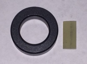
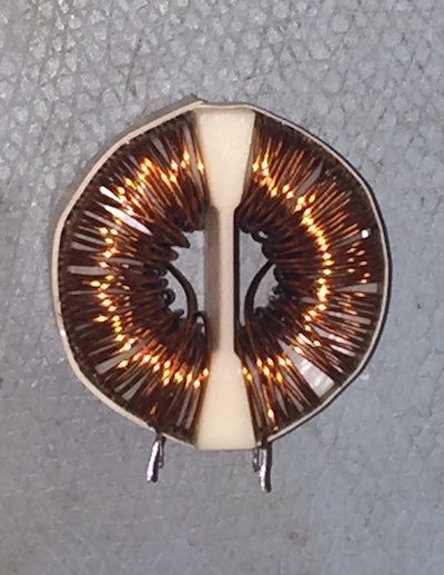
I got some new ferrite toroidal cores from RS-Components and wound a new filter in the newer style, placing a piece of fibreglass PCB material in the centre of the core to isolate the Active and Neutral windings.
The new filter with separated Active and Neutral windings
Due to differences in the permeability of the core the inductance wound up (TIC) at only 700uH now instead of the expected 3mH I was aiming for. I decided to fit that anyway and it seems to be working fine.
The filter was inserted into the back of the PCB to hold the wires firmly while I heat the heatshrink down to fit.
A much neater fit than either of the original filters in the limited space
Vulcan Katra* implant
*Katra is the Star Trek (TM) Vulcans mind or soul which can be transplanted into another person via a mind meld, usually before death.
I tried to boot it up as I had done with the other card, but got nothing. Wondering if all the ICs were working I decided to perform a mind meld and swap all of them into the working Vulcan IIGS board that I had already tested. It still failed to boot meaning that one or more of the ICs was faulty. After a lengthy process of swapping a few ICs at a time I eventually determined that IC U7-74LS245 was faulty, so I installed a new 74LS245 from my stash of ICs into the test setup and it booted fine. With all the ICs known to be working I reinstalled them back into the faulty board and tried it again.

Time to celebrate with some Apple Cider before I move onto the next Vulcan rescue.
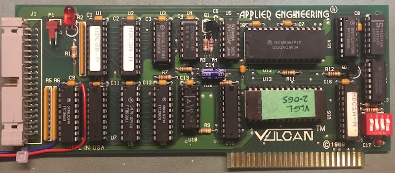
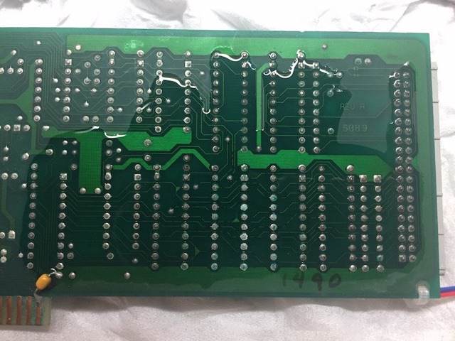
Once I was satisfied with the Vulcan IIGS operation I then moved to the Vulcan //e interface, which had a VUL1.4E40 EPROM fitted. I reconfigured it for a IIGS by swapping in a known good VLGL2.0GS ROM and added a +5V power lead for the IDE-CF adapter. I noticed that there were signs of corrosion on the back of the PCB affecting about a quarter of the board, but initially I ignored that.
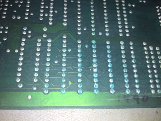
Some corrosion on the IC legs. You can also see dark traces in some areas, not a good sign.
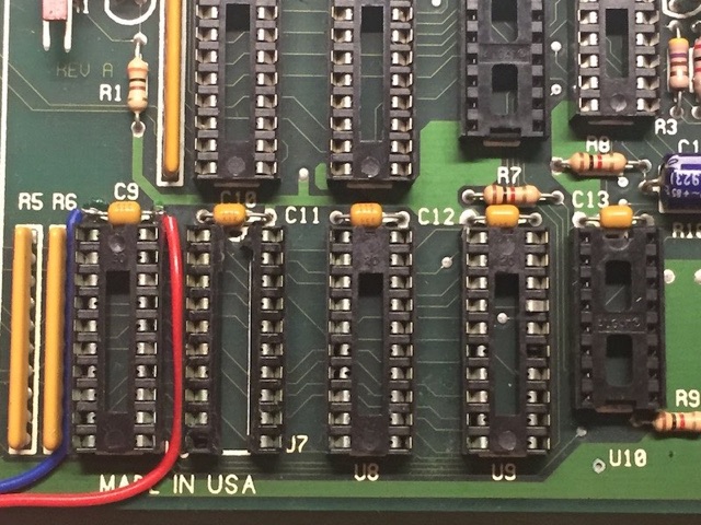
The original IC sockets just as I was removing them. Note: some pins are broken and some are corroded inside the socket.
All the now working ICs re-nstalled
It still wouldn’t boot so I removed the board and examined the tracks on the back of the PCB with a 10x eyeglass, and noticed that the corrosion was worse than I had thought. Applied Engineering had used very thin tracks, some about 5mil (0.005”) in width and many of those had black spots in them under the solder mask. So it must have crept through the tracks over time.
I suspected that a nearby alkaline battery in an adjacent slot (such as a clock card) had leaked and it eventually crept across to this board. I’d hate to see how that worked out for the other card, not well I suspect. I later found that the original owner had an adjacent AE Serial card with a battery that had leaked.
A layer of white vinegar is carefully applied over the affected areas
I needed to clean the back of the PCB to help with the removal of the IC sockets and potentially remove some of the corrosion. IsoPropyl Alcohol (IPA) is ineffective at removing corrosion, so for the first time I used white vinegar dripped sparingly on the back of the PCB and only in the affected areas. The vinegar acts as a mild acid and will dissolve some of the corrosion away. You can see it reacting with the corroded areas or any exposed copper. After only a short while I dried it all off and re-cleaned it with IPA to stop the reaction. Overall there was some improvement, especially around the solder pads and pins, but tracks damaged under the solder mask were not improved. I would not recommend this method be used as a routine cleaning method unless as a last resort.
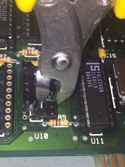
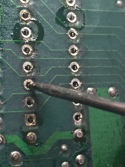
After removing several ICs in the affected areas around U6, U7, U8, and U9 I ran some continuity tests with my multimeter and discovered 10 tracks that were open circuit. I also found a few pins in some of the IC sockets had corroded and broken off, so I decided to replace all 4 of the sockets with machine pin IC sockets that I had in stock.
Removing the sockets can cause more damage if you are not careful. One thing I do is add solder to the pin first to help with heat transfer, then desolder with a vacuum desoldering station. I then use a wriggle test on each pin to make sure it’s not still hanging on. If the pin doesn’t move then I go back, add more solder and try to desolder again. If you only use solder wick you will be sadly disappointed as it rarely gets all the solder out of the holes and your part is stuck in the PCB.
If the pins wont desolder after a few attempts there is a plan B...
Since some pins won’t desolder I resort to cutting the socket
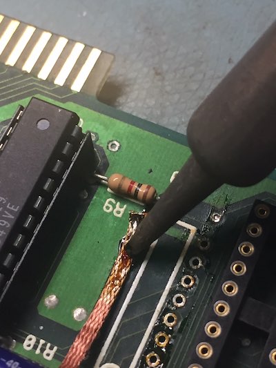
Desolder wick soaked in Rosin flux helps mop up the solder as you drag it across the pads slowly with a soldering iron
Using a pair of side cutters to cut the socket into smaller pieces can help remove it. After cutting it the pin can be heated and pulled while hot. It’s a better option than just pulling the socket or pin out cold, which can lift solder pads off the PCB and then you are in a far worse situation. Once I’ve removed the sockets I clean up the pads using liquid rosin flux and solder wick.
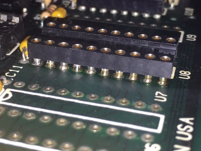
Machine pin IC sockets used to replace the dual wipe sockets at U6..U9
One advantage of machine pin IC sockets is being able to see if the top connection is good
back of PCB with 10 jumpers installed
I reinstalled the ICs again for another test but while it seemed to get further into the boot process it eventually crashed. Once again I removed the board and checked some more tracks, finding 4 more had failed, mostly where they passed between pins on the sockets I had replaced. Because they were already compromised with corrosion I suspect that they gave out while I was desoldering the old sockets.
In the end I replaced a further 2 IC sockets and added another 4 jumper wires. The wire I use is thin insulated wire wrap wire which is very small and its diameter is lower than the height of the IC legs protruding through the board.
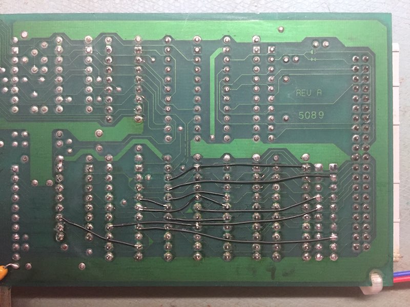
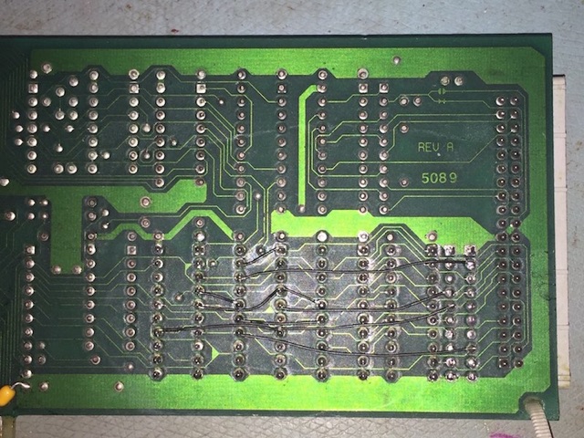
An extra 4 jumpers are added
Once again I refitted the ICs and retested the board and this time it booted up fine and has been running for several hours. I’ve concluded that the board is serviceable, however it is possible that a few more tracks will have to be jumpered in the future.
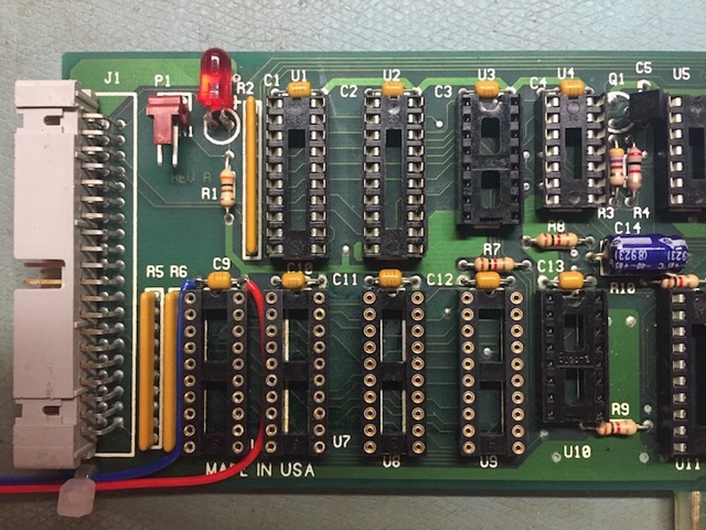
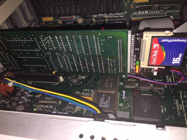
The repaired Vulcan interface with a 16M SanDisk CF card installed. You can barely notice the black jumper wires.
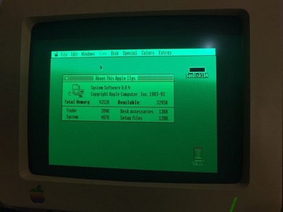
Booting GS/OS 6.0.4 for a test run
While I had the ICs and sockets removed from the board I took the opportunity of documenting part of the PCB overlay, which I have attached here. It is incomplete and unchecked but may be useful in some way. It is not likely that I will complete this overlay in the near future unless someone else needs work done on their board. It is very difficult to remove the ICs or other parts on these boards because the holes for the IC legs are not much bigger than the legs of the ICs, and doing so risks damaging the boards unnecessarily. For this board it was necessary to remove the ICs and sockets because of extant damage.
I hope this repair tale will encourage you to never give up on repairing these old computers. I learned a few new tricks with these two repairs and would like to thank those in the Apple II community that helped along the way. A special thanks to Craig who loaned me his rare Vulcan PSUs and controllers without which my broken PSU may have been lost to Shariel.
MC
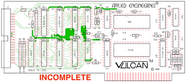
Incomplete PCB Overlay
Wriggle test
Plan B, get Medieval...
