
Not another Apple II PSU document, does it ever end ? Not yet apparently. This is for the ASTEC AA11040C version of the PSU which was installed in my un-enhanced Apple //e but were also fitted to the Apple II europlus according to my sources.
by Mark Cummings
It seems like it was less than 24 hours ago in the wee hours that I published my version of the Apple IIGS 240V ASTEC PSU Circuit Diagram and here I am again with an Apple //e, Apple II europlus ASTEC PSU circuit diagram.
Dean Claxton and I have already documented the Dynacomp 240V PSU here a few years ago but now the circle is almost complete with the earlier ASTEC Power supply which was fitted in my un-enhanced Apple //e (the model with the thick painted case).
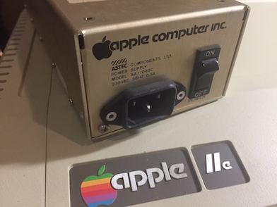
240V ASTEC Power Supply (removed from my un-enhanced Apple //e)
I believe the AA11040C is also fitted to the Apple II europlus as well as the almost identical AA11040B.
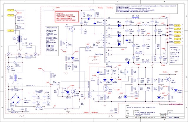
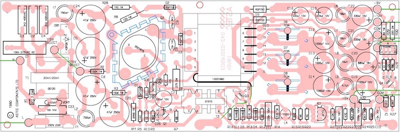
Once again I did my internet research and found very good circuit diagrams for the AA11040B power supply including an OEM one on the mirror web site to appleii-box.de. I also found fairly good close up images of a 240V AA11040C power supply board on tolderlund.eu web site. Although there was no requirement to make my own version of these diagrams I did find a couple of errors on the OEM circuit and also wanted to produce a version with the track work visible through the overlay as I have for other overlays in the past. I find them easier to follow how the components are connected under the board while viewing from the top especially when tracing faults or checking voltages. Another thing I didn’t like about the OEM version is the way the primary and secondary side of the circuit is overlapping in the middle.
The OEM circuit was and still is very useful as it also includes AC waveforms as they would appear on an appropriately isolated CRO, something which is lacking in my own diagrams.
Circuit Diagram created with Protel Schematic application
In the above test setup, CH1 on the CRO is connected to the input signal and is used as the trigger for the CRO. CH2 is connected to the output of the tank circuit. By generating a signal on the RF signal generator and injecting it into the tank circuit, the frequency which has the highest amplitude at the output of the tank circuit determines the resonant frequency of the circuit.
Adjust the frequency on the RF Signal Generator and look for a peak amplitude signal on the output (CH2).
From that you can use the resonant frequency formula (or a web based resonant frequency calculator) to calculate the inductor value. As an example given a 10uH inductor and 10nF capacitor the resonant frequency is about 503.3KHz. With an unknown inductor simply adjust the frequency on the RF Signal generator until the maximum amplitude signal is observed on CH2, then record what the frequency is on your signal generator or CRO and then use the formula f = 1 / (2π √L C) to estimate the inductor value. There will be a bit of an error due to test cable capacitance and inductance and component tolerances, however the results are more accurate than my LCR meter could read.
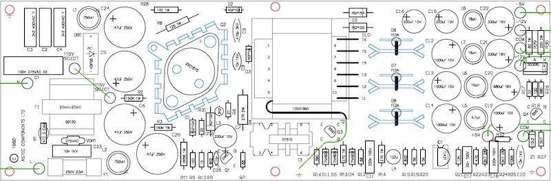
PCB composite overlay generated from Protel PCB Application
A mostly Black and White overlay without the underlying track work
The all important Part List with extra information on some parts.
If you are not competent then get help from someone who is.

Once again I hope these diagrams and parts list will be of use if you ever have to work on your power supply. If you do find any errors or variations with your power supply please send me details by email (address in the diagrams) so I can update this page.
MC
One thing missing from many of the extant diagrams in the wild is a lack of part information. I couldn’t find any diagrams or lists of parts detailing the inductor values. I decided to remove many of the inductors so I could measure them myself and this is where I ran into a small problem. My el-cheapo LCR meter has very poor accuracy and resolution for anything under about 50uH. This may be true of other LCR meters too. After some research I found that there is a couple of ways to test small value inductors. I chose to build a small tank circuit (also known as a band pass filter) on a piece of strip board which is just 3 components (a resistor, a capacitor and the inductor under test). A resonant circuit oscillates at the frequency determined by the value of the inductor and the capacitor in the circuit using the formula f = 1 / (2π √L C) where f is the resonant frequency, C is capacitance and L is the inductance.
Top view of the PCB after removing the top of the enclosure


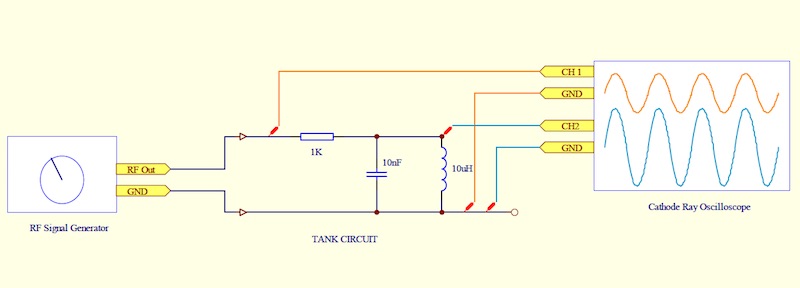
A diagram of a tank circuit and how it connects to test equipment
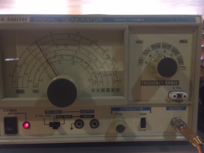
An old Dick Smith RF Signal Generator used for the test circuit
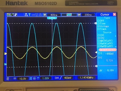
A modern CRO used for test circuit showing the source signal input (Yellow trace) and the signal level at the output (Blue trace).
Note the frequency is automatically displayed on the CRO in the bottom right corner.
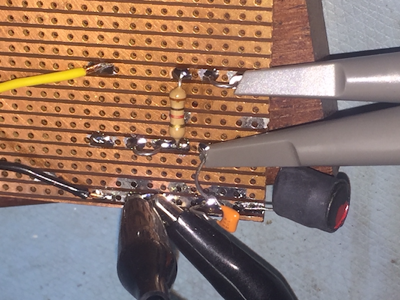
1K resistor, capacitor and inductor under test soldered onto a piece of strip board
Yellow and black wires are the signal input from the RF Signal Generator
Although I no longer have an Apple II europlus or Apple II Plus, I am advised that they also use the AA011040C and AA11040B power supplies.
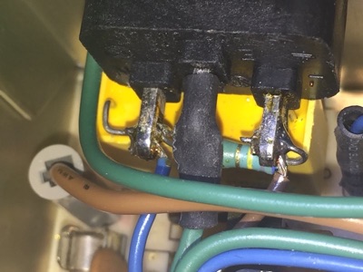
One difference I have noticed is that my power supply has an extra 0.47uF 275VAC X2 MKT capacitor and 680K 1/2W resistor soldered directly across the Active and Neutral pins on the back of the IEC power entry socket. I don’t know if these are fitted in all AA11040C supplies or whether this is a late modification, however my supply appears to have been done by the OEM. I have since replaced the X2 capacitor so as not to have a repeat smoking incident with a RIFA capacitor. After all, these supplies are 35+ years old.
It is important to note that the X2 capacitor is before the power switch in the circuit, so if it decides to fail and smoke, switching the power off at the PSU switch does NOT remove power from the capacitor. You would have to switch it off at the wall where your cord plugs in.
Close up of power entry socket showing a new X2 capacitor and original bleed resistor hidden underneath the wires
V 1.1
UPDATED 10 Apr 2020
UPDATED 10 Apr 2020
V 2.0
V 2.0
