
Apple // enthusiasts reverse engineer the DynaComp 240V Power Supply
The Apple //e power supplies suffer common failures just like many other pieces of 30 year old electronic equipment.
Power Supplies for the Apple // series of computers were manufactured by ASTEC and DynaComp. ASTECs were predominantly fitted to the earlier Apple II europlus, beige Apple //e and enhanced //e, while the Dyna Comps were predominantly fitted to the Platinum //e.
by Mark Cummings
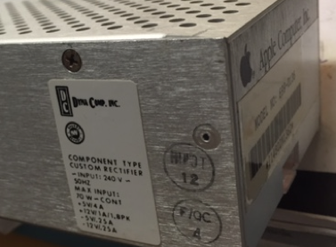
240V DynaComp Power Supply case.
(typically installed in the Platinum //e)
Although Apple published circuit diagrams of the motherboards in various hardware reference manuals, no such resource existed for ancillary components manufactured by third party manufacturers, such as the power supply. Long time Apple // enthusiasts and full time technicians Dean Claxton and Mark Cummings while independently repairing some ASTEC and DynaComp power supplies decided to pool their efforts in creating a circuit diagram and PCB overlay to assist in fault finding. After a lot of email traffic over a couple of months the results are finally in.
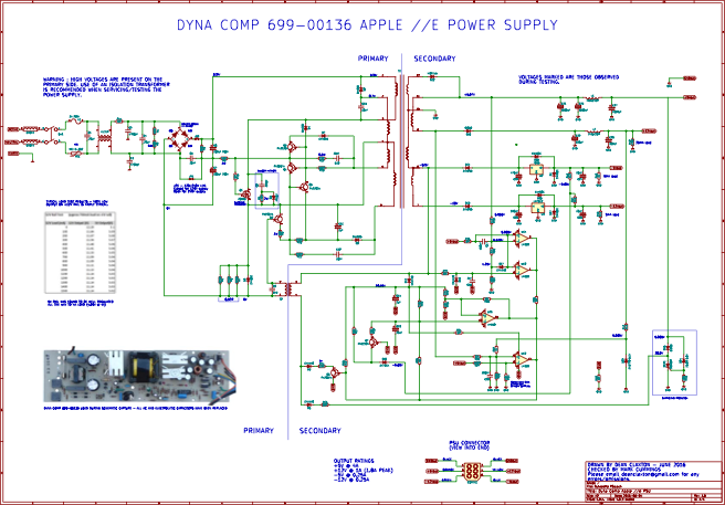
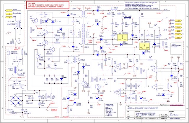
There is no one way to fault find a circuit, and without a diagram it is far more difficult. One approach without a diagram is known as the ‘shotgun’ technique. This is often used when you have absolutely no idea where to start. It may or may not get the job done, but can be time consuming and costly, both in time and money. The preferred approach is to use a circuit diagram and check voltages and waveforms in various parts of the circuit. The circuit diagram below will assist the average technician repair the DynaComp PSU.
Circuit Diagram created with KiCAD application
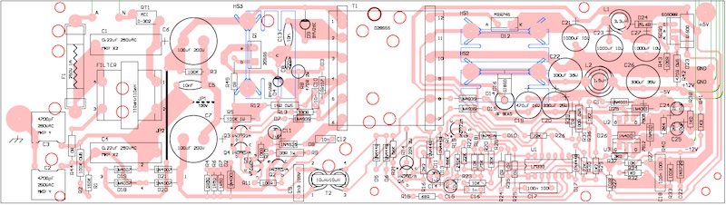
Having a circuit diagram is great, but unlike the ASTEC PSUs, the DynaComp power supply has no screen printed overlay on the PCB identifying the component designators. This can make finding the parts on the diagram time consuming. The diagram below will help locate where on the board those parts are saving time and reducing the chance of errors. The designators are unlikely to be the same as the original manufacturers designations, but Dean and Mark have matched the circuit to the PCB overlay. Hopefully there are no errors, but if you do find any, contact details for Dean or Mark are included in the diagrams.
PCB composite overlay generated from Protel PCB Application
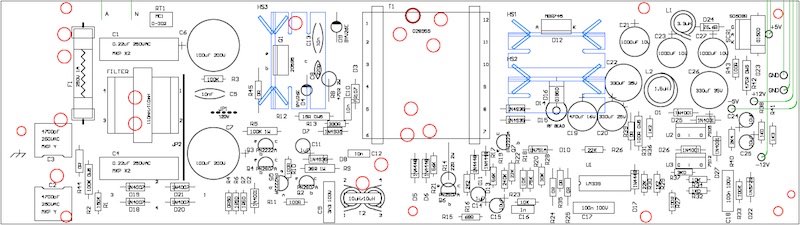
A more traditional PCB top overlay
Many of the components, especially the diodes, had their part numbers worn off making identification difficult. In order to identify all the parts it was necessary to remove some, measure and and examine them close up with a 10x magnifying eyepiece. The parts list below was originally generated by the Protel PCB application after the overlay was finished. Additional information was obtained from the manufacturers data sheets, most of which are freely available on the internet.
Detailed Parts list
An ESR meter can be used to check the internal resistance while the capacitor is still fitted to the board. This is a real bonus as it is relatively quick to measure all the capacitors on a board, removing only those that exhibit a high or suspect high ESR.
However before you can check the capacitor’s ESR you will need to remove the board from the case because all of the electrolytics in the supply are radial type and the only easy way to access them is to measure them on the bottom of the board.
As with most electronic circuits there is an element of danger. With power supplies it is the 240V mains side that can cause harm with DC voltages reaching 340V. A few precautions should be taken.
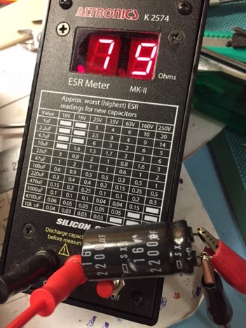
An Altronics ESR meter measuring a failed 2200uF 16V capacitor with a very high ESR.
Common faults in the power supplies
Before removing the supply and opening the PSU enclosure the power cord should be removed then wait a couple of minutes. By design the internal voltages should bleed off the high voltage capacitors through bleeder resistors.
However to be sure, in case the bleeder resistors have failed, you should also short out the mains capacitors with a conductive tool that has an insulated plastic handle, such as a screwdriver.
Doing this may require special care when removing the board from the case. If you don’t understand the risks and the precautions you should seek assistance or leave it to someone that does.
Once the PCB is removed the ESR of all the capacitors can be measured without removing one part. Take note of any that are above what would be typical for that capacitor. The chart on the ESR meter is only a guide and manufacturer data sheets are the ultimate reference.
UPDATE: The ESR values are now included on the PCB overlay
MC


Considering the relatively high temperatures inside most Apple // systems, and that cooling fans were never installed by Apple, one of the most common failures are with electrolytic capacitors.
Measuring the capacitance of a capacitor with a traditional capacitance meter may reveal a fault, but often the capacitance is in the normal range.
Also in order to measure the capacitance it is necessary in most cases to remove the capacitor from the PCB as other components in the circuit will affect the reading. Capacitors have a tendency to dry out in high temperatures and their internal resistance, known as the Equivalent Series Resistance (ESR) also goes high.
UPDATED 08 Apr 2020
Original Schematic V1.0
Alternate Schematic V2.0
Circuit Diagram created with Protel Schematic application
V 2.0
V 2.0
Identifying the parts
UPDATED 08 Apr 2020
UPDATED
05 Apr 2020
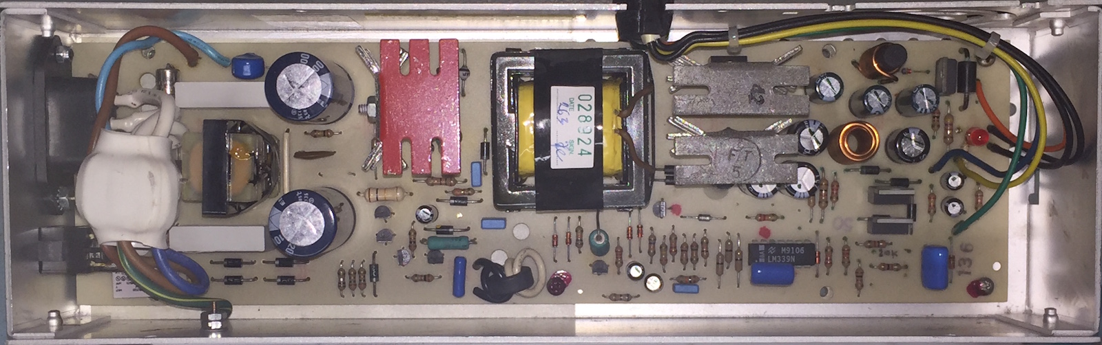
Top view of the PCB after removing the top of the enclosure
